Sky cleaner III
Written by Houxiang Zhang
As Technical Coordinator of the project “Glass-wall Cleaning Robots for High-rise Buildings”. The pneumatic robot named Skycleaner 3 has been developed and put to good use at the Shanghai Science and Technology Museum.
Key activities: System design; Pneumatic system design and manufacture; Research on pneumatic position control.
This project supported by “Beijing Science Committee project” was implemented at Robotics Institute in Beihang University (BUAA).
Sky cleaner 3 is a real product designed for cleaning the complicated curve of the Shanghai Science and Technology Museum in 2001. The building top is 40 m from the ground. From the left to the right its height gradually decreases. The total surface area of the outer wall is about 5000 m2. Due to the special arc shape, each glass is connected to its surrounding glasses at about a 2-degree angle.
The robotic system consists of three parts: 1) a following unit; 2) a supporting vehicle; 3) the cleaning robot. The robot is supported from above by cables from the following unit mounted on the top of the building. All following movements of the unit which protects against falling due to any type of failure are synchronized by the robot itself.
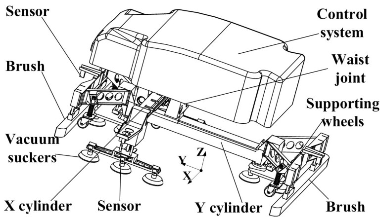
Because the glass walls of the Shanghai Science and Technology Museum have no window frames, there are some supporting wheels near the vacuum suckers in the X and Y directions, which have been added to the mechanical construction to increase the stiffness. In order to move from one column of glass to another in the right-left direction, a specially designed ankle joint gives a passive turning motion to the suckers. This joint is located between the connecting piece which joins the vacuum suckers with the Y cylinder and the plank beneath it to which 4 vacuum-suckers are attached.
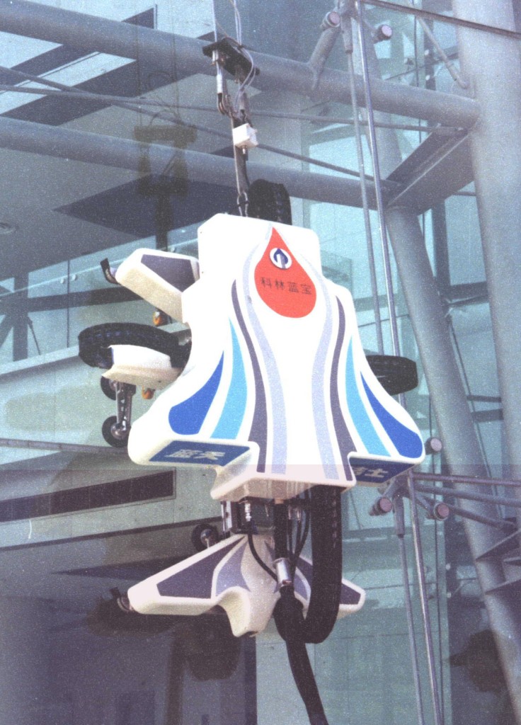
A PLC is used for the robot control system, which can directly count the pulse signals from the encoder and directly drive the solenoid valves, relays and vacuum ejectors. FX2N-4AD which is added to the system can identify the sensor analog signals. The control and monitoring of the robot is achieved through the GUI to allow an effective and user friendly operation of the robot. The communication interface between the PLC and the controller of the following unit is designed to synchronizing the following movement of the cables. The sensors on the robot can be divided into external and internal sensors. The external sensors are responsible for collecting information about the operational environment. The internal sensors are to reflect the self-status of the robot. There are two kinds of external sensors on the robot: touchable sensors and ultrasonic analog sensors. For each active joint, there are limit switches to give the controller the position of the joint. On the joint where the accurate position is needed, the optical encoder is used. The vacuum sensors are used to monitor the vacuum condition of the suckers and provide information to determine whether the suction on the glass surface is stable. Fig. 2 shows the robot is working on the glass walls of this museum.