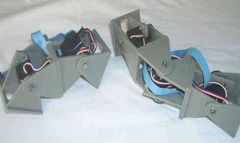
Y1 Module
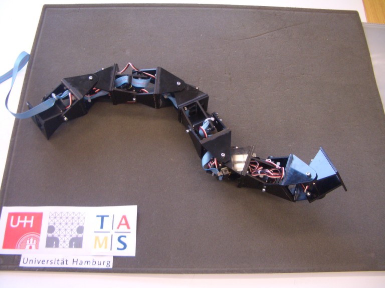
Since 2004, our international group began to work on low-cost passive modular robots. The Y1 modular robot with one DOF in Fig. 1, was designed by our project cooperator Ph.D. Juan Gonzalez-Gomez in 2004 as the first prototype. Using this prototype, the minimal configurations for movement are studied. Then two eight-module robots were built for further research purposes. One is a pitch-connecting modular robot and the other a pitch-yaw connecting robot, as shown in Fig.2.
Using docking blots, the modules can connect or disconnect easily and flexibly. Each joint actuated by a RC servo is controlled by means of a sinusoidal oscillator with four parameters: amplitude, frequency, phase and offset.
The Y1 module is made of plastic so that the stiffness of its mechanical structure is quite low. The module breaks very easily since all of tits mechanical parts are glued together without any professional connecting components.
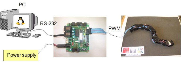
The control of our modular robot is based on sinusoidal generators to produce rhythmic motion. From the biological point of view, these generators act like the Central Pattern Generators (CPGs) located in the spinal cord of the animals to control variation of the rotation angle of each module.
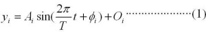
The sinusoidal generators produce very smooth movements and have the advantage of making the controller much simpler. Our model is described by the following equation (1). Where yi is the rotation angle of the corresponding module; Ai is the amplitude; T is the control period; t is time; ø is the phase; Oi is the initial offset.
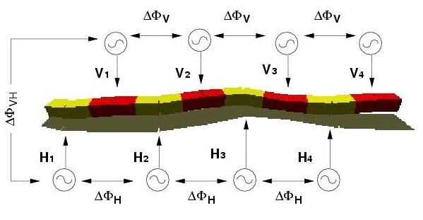
The last picture shows a sketch map of the control algorithm. Eight sinusoidal generators are represented to actuate all modules to rotate. According to the connecting relationship of the modules, they are divided into horizontal and vertical groups, which are described as Hi and Vi respectively. Where i means the module number; ΔV is the phase difference between two adjacent vertical modules; ΔH is the phase difference between two adjacent horizontal modules; ΔHV is the phase difference between two adjacent horizontal and vertical modules.